The intent of this project is to gather and assess alternative measurement systems. The process of designing a new idealized system will include comparing new technologies and previous Nuclear Regulatory Committee (NRC) approved methods. The goal of this project will be to consider reliability, cost effectiveness, and simplicity to design an improved downcomer water level measurement system. This project will culminate in providing GEH a recommendation for the BWRX- 300 system.
Team: Nathan Peck, Rida Rahman, Madison Wagner, Benjamin Zawislak
Project Advisors: Mr. Charlie Heck (GE) & Professor Malaviya

Members of the design group
Project Motivation
This project is concerned with upgrades to the General Electric-Hitachi (GEH) BWRX-300, which is the company’s small modular reactor. This project specifically focuses on the downcomer water measuring system. The current system uses legacy dual manometers to measure the pressure in both the subcooled and saturated sections of the downcomer. The flaws in the system are the high number of taps it requires, its limitations for loss of cooling accidents (LOCA), and maintenance challenges. GEH tasked the team to find a simpler, more cost effective solution that can be used in the old system’s place.

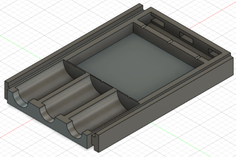
Figure 1- Fusion CAD model of transducer case. The case holds 3 transducers. It is complete with clots for the electrical wet connection and rails to slide into mounted tracks.
Project Description
The intent of this project is to gather and assess alternative measurement systems. The process of designing a new idealized system will include comparing new technologies and previous Nuclear Regulatory Committee (NRC) approved methods. The goal of this project will be to consider reliability, cost effectiveness, and simplicity to design an improved downcomer water level measurement system. This project will culminate in providing GEH a recommendation for the BWRX- 300 system.

Figure 2 – CAD model of wet connection with “plug and play” capability. The figure shows how the casing slides right into pre-positioned connectors.

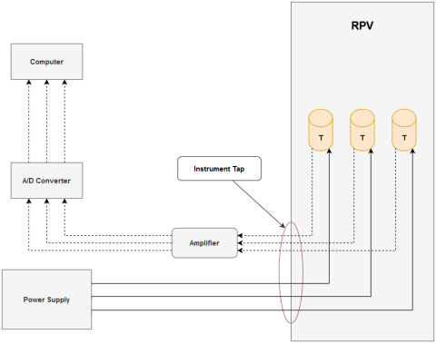
Figure 3- Wiring diagram for transducers. Electrical signals from transducers will travel through an amplifier and converter in order to calculate water level.
Results and Accomplishments
The design the team has recommended is a train of wired transducers and thermocouples. The design was chosen over an updated manometer system and a RADAR system. The transducer train has been split into the subsystems of casing, data collection, and data processing. The system includes a single, removable case containing three transducers placed into permanent railings at the bottom of the downcomer. The transducers communicate with a database of thermodynamic principles of pressure and temperature to calculate the water level, with the goal of being accurate within an inch.